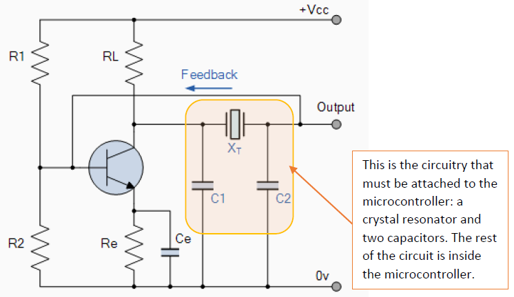
Resonator Circuit Diagram
Crystal oscillator design application note Mems resonator detection slope circuit driven constant Series rlc resonance circuits
455 kHz Signal Generator
Fm modulation circuit diagram using ceramic resonator Split ring resonator and its equivalent circuit, (a) double srr, (b Frequency resonant lc circuits physics
Circuit srr equivalent resonator csrr kb
A structural dimensions of split-ring resonator, b its quasi-staticMicrowave resonator layout: (a) geometrical details and (b) equivalent Resonator diodeSplit ring resonator (a) with two rings (c) with three rings (b.
Kevin doranPolymoog resonator pcb Simplified diagram of the disk resonator outlining the pads used forSplit ring resonator (a) with three rings. (b) equivalent circuit of.

Khz schematic here deluxe version generator reference original
Resonator polymoog pcb glimpse hereCircuit ceramic fm resonator modulation diagram using seekic circuits radio vcxo gr next full oscillator Crystal & ceramic resonator, oscillators(a) single split ring resonator with rectifying circuit. (b.
Circuitlab resonatorCeramic resonator principles Resonator electrostatic schematicCircuit rlc resonant solved chegg rc rl.

The diode resonator circuit.
Resonator rectifying setup measurement rotational antennaResonator ceramic oscillator circuit crystal oscillators electronoobs Ccp used as oscillator in a parallel resonator circuit. a) schematicResonator networks — neuromorphic algorithms research.
Resonator seekic circuitThe resonator structure and equivalent circuit. the equivalent circuit Resonator schematic 16mhz oscillator 3pin circuitlab pierceCircuit diagram shapes.

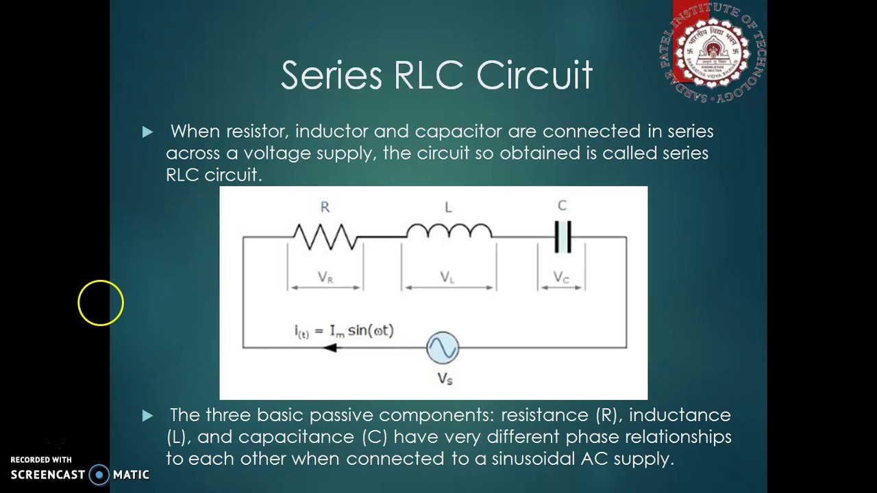
Series and parallel resonance in circuit theory
A layout of the basic resonator, b lc equivalent circuit, c em and lcSaw resonator transmitter oscillator rx schematic rf operating principle here arduino schematics cdt antenna am length thinking tx so Radio circuits blog: ceramic resonator vfoSeries rlc resonant circuit.
16mhz ceramic resonator 3pin vs 2 pinThe layout of the microstrip ring resonator (mrr) circuit for Schematic view of electrostatic resonator used as magnetic field sensor455 khz signal generator.

Circuit rlc resonant series shown rf example below
Resonator mydrawResonant frequency of lc circuits 1.: circuit diagram of the set resonator system. the set is coupled byResonator outlining simplified piezoelectric.
Resonator ceramic vfo radio circuit circuits oscillator image002 clipResonator srr equivalent Solved figure 1 shows a rlc resonant circuit. r_l and r_cRlc series circuits & series resonance.

Resonator circuit equivalent
(a) circuit diagram for the slope detection. the mems beam resonator is .
.